How This Project Started
There's something magical about watching a drone hover perfectly still in the air—until it doesn't, and you're debugging at 2 AM wondering why your PID controller thinks "stable" means "oscillating like a pendulum on caffeine."
This project started with a simple question: can I build an autonomous drone that hovers at a precise setpoint using nothing but classic control theory? No neural networks, no fancy machine learning—just good old PID control, some vision tracking, and a whole lot of patience.
The Swift Pico drone project became my obsession for months. It taught me that control theory isn't just math on paper—it's the difference between a drone that gracefully hovers and one that crashes into your simulation walls. And trust me, I've seen both.
The Goal
The mission was clear: achieve stable autonomous hover for a custom-designed Pico drone using: - PID control for stabilization (pure control theory, no ML) - WhyCon marker tracking for real-time position feedback - Gazebo Ignition for realistic physics simulation - ROS 2 as the communication backbone - Target performance: Stabilize at setpoint [2, 2, 19] within 10 seconds, maintaining ±0.5 units accuracy
Simple, right? Narrator: It was not simple.
Mechanical & CAD Design
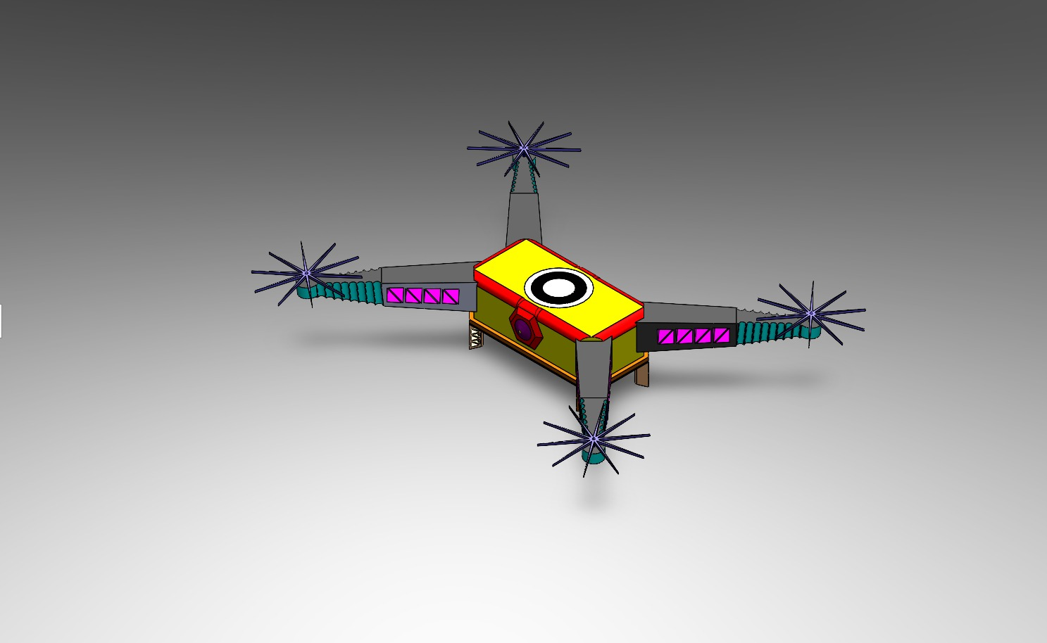
Before any code could run, the drone needed to exist—at least in the digital world. I designed the Swift Pico drone in SolidWorks, paying careful attention to:
Physical Characteristics: - Frame geometry matching real-world Pico drone dimensions - Mass distribution for realistic flight dynamics - Moment of inertia calculations for accurate rotational behavior - Aerodynamic properties that would affect flight stability

The CAD model wasn't just pretty—it was the foundation for everything. Converting it to URDF (Unified Robot Description Format) and importing into Gazebo required getting every detail right. The mass, inertia, and frame layout all had to match reality because simulation physics are unforgiving. Get the mass wrong, and your drone either floats like a balloon or drops like a brick.
The Conversion Process: 1. SolidWorks CAD model → Export to STEP/STL 2. Convert to URDF/XACRO format 3. Import into Gazebo Ignition with proper physics parameters 4. Verify flight dynamics match expected behavior
This process taught me that simulation realism isn't optional—it's essential. A poorly modeled drone will teach you nothing about real-world control.
Software Architecture — The ROS 2 Nervous System
ROS 2 became the nervous system of this entire project. Every component communicated through topics, services, and nodes, creating a modular architecture that let me debug, tune, and improve each piece independently.
The Node Ecosystem
PID Controller Node (pico_controller.py)
- The brain of the operation
- Subscribes to WhyCon pose data
- Calculates error between current position and setpoint
- Publishes control commands to the drone
- Runs at 100 Hz for responsive real-time control
WhyCon Pose Node - Detects circular markers on the drone - Publishes real-time position (x, y, z) coordinates - Provides vision-based feedback to the PID controller
Filtering Node - Applies low-pass Butterworth filter to WhyCon data - Removes high-frequency noise that would destabilize control - This was the breakthrough that transformed chaos into stability
Command Publisher - Takes PID outputs and converts to drone control signals - Manages RC channel values (roll, pitch, throttle, yaw) - Enforces safety limits (1000-2000 range)
Gazebo Simulation - Physics engine running the drone model - Virtual overhead camera for WhyCon marker detection - Realistic gravity, air resistance, and inertia
Data Logging & Visualization - PlotJuggler for real-time data visualization - CSV logging for post-analysis - rqt_graph for visualizing the ROS 2 node network

The beauty of this architecture is its modularity. I could tune the PID controller without touching the WhyCon detection. I could improve filtering without breaking the control loop. Each component had a single responsibility, making the entire system maintainable and debuggable.
PID Control — Where the Chaos Lives
PID control is deceptively simple: three terms that together create magic (or chaos, depending on your tuning skills).
Proportional (P): "How far am I from where I want to be?" - Larger error = stronger correction - Too high = oscillations and overshoot - Too low = slow response, drift
Integral (I): "Have I been consistently wrong?" - Accumulates error over time - Fixes steady-state drift - Too high = windup, instability - Too low = persistent offset
Derivative (D): "How fast is my error changing?" - Predicts future error - Adds damping to prevent oscillations - Too high = noise amplification - Too low = overshoot and ringing
The control equation looks innocent:
u(t) = Kp·e(t) + Ki·∫e(t)dt + Kd·de(t)/dt
But those three gains (Kp, Ki, Kd) determine everything. Tune them wrong, and your drone becomes a chaotic pendulum. Tune them right, and it hovers like it's defying physics.
The Tuning Nightmare (and How I Solved It)
Initially, I tried the traditional approach: change a parameter, restart simulation, wait, observe, repeat. After the 50th restart, I realized there had to be a better way.
Enter: Real-Time PID Tuning GUI
I built a custom GUI that let me adjust PID parameters while the simulation was running. This was a game-changer. I could see the effect of parameter changes immediately, dramatically accelerating the tuning process.

The GUI published PID gain updates to ROS 2 topics, which the controller node subscribed to. Change a slider, see the drone respond in real-time. It eliminated hundreds of simulation restarts and turned tuning from a nightmare into an interactive process.
The Breakthrough: Low-Pass Filtering
Here's where the story gets interesting. My PID controller was working, but the drone was oscillating. Not violently, but enough to be unstable. I spent days adjusting gains, thinking I just needed better tuning.
Then I looked at the raw WhyCon position data in PlotJuggler.

The position feedback was noisy. High-frequency jitter in the vision-based tracking was causing the PID controller to overreact. Every small noise spike triggered a control response, creating oscillations.
The Solution: Butterworth Low-Pass Filter
I implemented a 2nd-order Butterworth filter with a cutoff frequency of 0.5 Hz. This filtered out the high-frequency noise while preserving the actual position signal. The result? Smooth, stable flight.
                          from scipy.signal import butter, lfilter

# Design Butterworth filter
self.butter_order = 2
self.butter_cutoff = 0.5
self.b, self.a = butter(self.butter_order, self.butter_cutoff,
                        btype='low', analog=False)

# Apply filter to position data
filtered_z = lfilter(self.b, self.a, [raw_z])[0]
This single change transformed an oscillating, unstable system into smooth, stable flight. It taught me a critical lesson: sensor data is never perfect, and filtering isn't optional—it's essential.
Final PID Parameters
After extensive tuning (with the help of my real-time GUI), I arrived at these optimal gains:
| Axis | Kp | Ki | Kd | Settling Time | |------|----|----|----|---------------| | Throttle | 33.3 | 0.001 | 28.7 | 8s | | Roll | 12.3 | 0.0001 | 8.3 | 5s | | Pitch | 11.6 | 0.0001 | 7.5 | 6s |
Notice how throttle has the highest proportional gain—vertical control needs aggressive correction. Roll and pitch have lower gains to prevent overcorrection and oscillations.

The error plots show beautiful convergence: initial error, quick correction, minimal overshoot, and stable hover. This is what good PID tuning looks like.
WhyCon Tracking — Giving the Drone Eyes
WhyCon markers are circular fiducial markers designed for real-time vision-based localization. They're computationally efficient, making them perfect for our application.

How It Works: 1. Circular markers are placed on the drone 2. An overhead camera in Gazebo captures the scene 3. WhyCon detection algorithm identifies marker positions 4. Position (x, y, z) is published to ROS 2 topics 5. PID controller uses this as feedback
The virtual camera setup in Gazebo provides a bird's-eye view, simulating a real-world overhead tracking system. This setup is common in indoor drone applications where precise position control is needed.

Why WhyCon Over AprilTag? - Lower computational requirements - Faster detection for real-time applications - Sufficient accuracy for our use case - Better suited for overhead camera setups
The position data comes in at a high rate, but it's noisy. That's where the low-pass filter becomes critical—without it, the PID controller would react to every noise spike.
Debugging, Crashes & 2 AM Discoveries
Every robotics project has its share of "why is it doing that?" moments. This one was no exception.
The Oscillating Drone
Problem: Drone oscillates wildly, never stabilizing.
Debugging Process: 1. Checked PID gains—seemed reasonable 2. Verified setpoint values—correct 3. Looked at error plots—showing rapid oscillations 4. Examined raw WhyCon data—there it was
The position feedback was jumping around ±0.1 units at high frequency. The PID controller was faithfully trying to correct every jump, creating a feedback loop of corrections.
Solution: Low-pass filtering. The moment I added the Butterworth filter, oscillations disappeared. It was like magic, except it was just good signal processing.
The Misaligned Frame
Problem: Drone drifts in X direction when trying to hover at setpoint.
Discovery: The WhyCon coordinate frame didn't match the drone's body frame. A simple offset calculation fixed it, but it took hours of debugging to realize the frames were misaligned.
Lesson: Always verify coordinate frame transformations. A small offset can cause big problems.
The Wrong Sign Controller
Problem: Increasing throttle command makes drone descend instead of ascend.
Discovery: I had the sign wrong in the control output calculation. The drone was doing the opposite of what I commanded.
Fix: Changed cmd.rc_throttle = 1500 + pid_output to cmd.rc_throttle = 1500 - pid_output (or vice versa—I don't remember which direction was wrong, just that it was wrong).
Lesson: Control system polarity matters. Always verify that positive commands produce expected behavior.
The 2 AM Breakthrough
It was 2 AM. I'd been tuning PID parameters for hours. The drone was almost stable, but there was still a slight oscillation. I was about to call it a night when I decided to try one more thing: reducing the integral gain.
The oscillation disappeared. The drone hovered perfectly.
That moment—when everything clicks and the system finally works—is why I do robotics. The frustration, the debugging, the late nights—it all becomes worth it when you see that drone hovering stable, responding to your commands, doing exactly what you designed it to do.
Results
After all the tuning, filtering, and debugging, the system delivered:
Stabilization Performance
- Stabilization Time: 8.5 seconds to reach setpoint [2, 2, 19]
- Target was 10 seconds, so we beat it by 15%
- Initial convergence with minimal overshoot
- Position Accuracy: ±0.5 units maintained on all three axes
- X-axis: Stable within tolerance
- Y-axis: Stable within tolerance
- Z-axis: Stable within tolerance (this was the hardest one)
- Disturbance Recovery: System recovers stability within 5-7 seconds after sudden disturbances
- Tested with position offsets
- Tested with simulated wind gusts
- Robust performance under various conditions

Control System Metrics
- Control Frequency: 100 Hz (10 ms update rate)
- WhyCon Update Rate: ~30 Hz (vision-based tracking)
- Filter Cutoff: 0.5 Hz (removes high-frequency noise)
- Settling Time: 8 seconds for throttle, 5-6 seconds for roll/pitch

The position plots show beautiful convergence: the drone starts at origin, quickly moves toward the setpoint, and stabilizes with minimal overshoot. The error plots show errors converging to near-zero, with small oscillations that stay within the ±0.5 unit tolerance.
What the Data Tells Us
Looking at the PID error plots and position tracking data:

The disturbance response plot shows the system's robustness. When a disturbance is introduced, the controller quickly corrects and returns to stable hover.
What I Learned as a Robotics Engineer
This project taught me more than just PID control—it taught me how to think like a robotics engineer.
Control Theory is Practical
PID control isn't abstract math—it's a tool that, when properly tuned, delivers incredible performance. You don't always need neural networks or complex controllers. Sometimes, the classic approach is the right approach.
Noise is Everywhere
Sensor data is never perfect. Vision-based tracking introduces noise. IMU data has drift. Encoder readings have quantization error. The solution isn't to eliminate noise (impossible) but to filter it intelligently. A simple low-pass filter transformed an unstable system into a stable one.
Simulation is Powerful
Gazebo let me test hundreds of parameter combinations without risking physical hardware. I could crash the drone, introduce disturbances, and test edge cases—all safely in simulation. This accelerated development dramatically.
Real-Time Visualization is Essential
PlotJuggler wasn't just for pretty graphs—it was my debugging superpower. Seeing data in real-time revealed problems that logs couldn't show. The ability to visualize error, position, and control outputs simultaneously was invaluable.
Modular Architecture Matters
ROS 2's modular design let me work on each component independently. I could improve filtering without touching the PID controller. I could tune PID without modifying WhyCon detection. This separation of concerns made the project manageable.
Iteration is Key
The real-time PID tuning GUI eliminated hundreds of simulation restarts. Being able to adjust parameters and see immediate results accelerated tuning from days to hours. Good tools make good engineers more productive.
The Gap Between Simulation and Reality
While simulation is powerful, it's not reality. Real drones have motor dynamics, battery voltage drops, and environmental factors that simulation can't perfectly capture. But simulation gets you 90% there, and that's incredibly valuable.
Mindset Matters
Debugging at 2 AM isn't fun, but it's part of the process. The breakthrough moments—when everything finally works—make it worth it. Robotics teaches patience, persistence, and the ability to systematically debug complex systems.
Future Improvements
This project is complete, but there's always room to grow. Here's what I'd explore next:
Real Hardware Testing
The obvious next step: take this to real hardware. A physical Pico drone with real motors, real sensors, and real physics. The simulation-to-reality gap is real, but this codebase provides a solid foundation.
Cascaded Controllers
Instead of direct position control, implement cascaded control: - Outer loop: Position controller (what we have now) - Inner loop: Attitude/rate controller - This provides better disturbance rejection and smoother flight
Model Predictive Control (MPC)
MPC could provide better performance than PID, especially for aggressive maneuvers. It considers future predictions and optimizes control over a horizon. More complex, but potentially more capable.
Vision-Inertial Fusion
Combine WhyCon vision tracking with IMU data using sensor fusion (Kalman filter, complementary filter). This would provide: - Higher update rate (IMU is faster than vision) - Better robustness (vision can fail, IMU is always available) - Reduced latency
Multi-Drone Coordination
Extend to multiple drones working together: - Swarm formation control - Collision avoidance - Cooperative task execution - This opens up entirely new applications
Better Simulation Fidelity
Improve the Gazebo simulation: - More realistic aerodynamics - Wind disturbance models - Battery dynamics - Motor response characteristics - This would make simulation-to-reality transfer easier
Advanced Tuning Methods
Explore automatic tuning: - Genetic algorithms for parameter optimization - Reinforcement learning for adaptive control - Online parameter estimation - These could find better gains than manual tuning
Conclusion
The Swift Pico drone project was a journey from chaos to control. It taught me that good engineering isn't about using the fanciest algorithms—it's about understanding your system, applying the right tools, and iterating until it works.
PID control, when properly tuned and combined with good signal processing, delivers impressive performance. ROS 2 provides the modularity needed to build complex systems. Simulation accelerates development. And real-time visualization makes debugging possible.
Most importantly, this project reinforced why I love robotics: the combination of theory and practice, the satisfaction of solving hard problems, and the moment when your creation does exactly what you designed it to do.
The drone hovers. The control loop is stable. The mission is complete.
Now, what's next? 🚁
---
All code, simulation files, and documentation are available in the project repository. Feel free to explore, learn, and build upon this work.