How This Eight-Legged Idea Crawled Into My Brain
Let me tell you about the moment I realized that walking—something we humans do without thinking—is actually one of the most complex control problems in robotics. I was deep in research papers about biomimetic locomotion, reading about how spiders coordinate their eight legs with an elegance that makes my own two-legged walking look embarrassingly simple, when it hit me: I needed to build one of these things.
This project started with pure curiosity. How do hexapod robots—six-legged walking machines inspired by insects and arachnids—actually work? How do they balance? How do they decide which leg to lift next? And most importantly, how do I make one that doesn't faceplant the moment it tries to take a step?
What began as academic curiosity quickly became an obsession. I dove into research papers spanning decades, from early hexapod designs in the 2000s to modern bio-inspired locomotion systems. My team and I scoured Google Scholar, reading summaries and conclusions, collecting design ideas, and trying to understand the fundamental principles that make these creatures so elegantly mobile.
The goal wasn't just to build a robot that walks. It was to understand the beautiful complexity of coordinated multi-legged locomotion, to translate biological principles into mechanical reality, and to create something that moves with the kind of purpose and grace that makes you forget you're looking at assembled metal and plastic.
What I Wanted This Spider Bot To Do
Before I could start building, I needed to define what "success" looked like. This wasn't just about making a robot move—it was about creating a platform that could demonstrate fundamental principles of legged locomotion.
Core Objectives
Stability First: The bot had to maintain balance during walking. This sounds obvious, but when you have six legs and need to lift some while keeping others grounded, the center of mass calculations get... interesting.
Gait Planning: I wanted to implement multiple gait patterns—the specific sequences of leg movements that define how the robot walks: - Tripod Gait: Three legs on the ground, three lifted—fast and efficient for smooth terrain - Wave Gait: Sequential leg movements—slower but more stable - Ripple Gait: Alternating leg patterns—good for navigating obstacles - Crawling Mode: Low, stable movement for challenging terrain
Terrain Traversal: The robot needed to handle more than just flat surfaces. Different gaits for different situations, with the ability to adapt its movement pattern based on what's underneath those six feet.
Forward Kinematics: Understanding how joint angles translate to foot positions in 3D space. This is where the math gets real—every joint rotation changes where that foot lands, and getting it wrong means your bot is doing interpretive dance instead of walking.
Simulation Integration: A Gazebo simulation that could test control algorithms before deploying to hardware. Because let's face it, debugging a falling robot is expensive. Debugging code in simulation? That's just smart engineering.
Mechanical Design — Legs, Linkages & Joints
The mechanical design of a hexapod is where theory meets reality, and reality is usually heavier than you think.
Leg Geometry & Degrees of Freedom
Each leg needed to be a 3-DOF system—three joints that give it the ability to position its foot anywhere within a working volume. The joints are arranged hierarchically:
This arrangement gives each leg its own spherical working space. Think of it like having six little robotic arms mounted to a central body, each one responsible for placing a foot in the right spot at the right time.

The complete six-legged assembly showing the symmetric leg arrangement and body structure.
CAD Structure & Assembly
The CAD design process was iterative—each version refined the geometry, improved the strength-to-weight ratio, and fixed the issues that only become apparent when you're trying to 3D print something at 2 AM.
The design includes: - Base/Chassis: Central body that houses electronics and provides mounting points for all six legs - Base Links: Root segments of each leg, connecting to the body - Middle Links: The "thigh" segments, transferring motion from the actuators - Leg End Segments: The "shank" components that terminate in feet

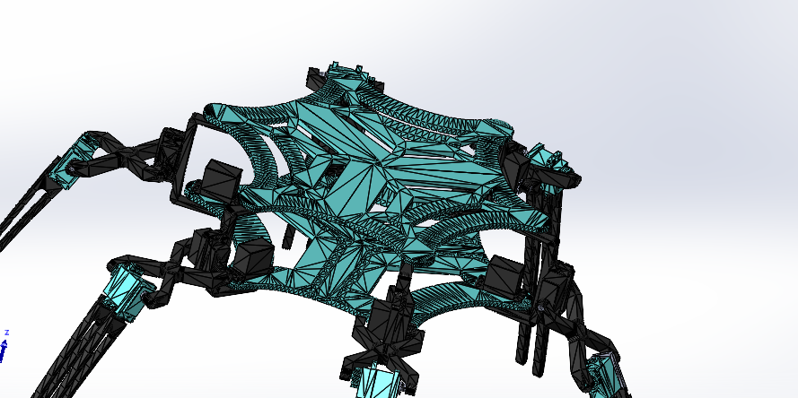
Detailed mesh view showing the geometric complexity of each leg segment and their interconnections.
The assembly process revealed something important: symmetry matters. Not just visual symmetry, but mechanical symmetry. Each leg needs to be identical in geometry and mass distribution, otherwise your control algorithms become a nightmare of exceptions and special cases.

Close-up view highlighting the joint mechanisms and mechanical linkages that enable coordinated movement.
Materials & Weight Considerations
Every gram matters when you're lifting six legs simultaneously. The materials needed to be strong enough to handle the dynamic loads of walking, but light enough that the actuators don't struggle under the robot's own weight.
3D printing became the fabrication method of choice—it allowed rapid iteration, complex geometries, and lightweight structures with internal reinforcement patterns. Each component was optimized for minimum mass while maintaining structural integrity.

Cartoon-style render showing the complete assembly in a more conceptual view, useful for understanding the overall structure.
Actuation & Control — Making the Bot Walk (And Not Fall on Its Face)
This is where the magic happens—or where everything goes wrong spectacularly.
Servo Mapping & Joint Control
Each leg has three servos, and we have six legs. That's 18 actuators that need to be controlled simultaneously, with precise timing, coordinated sequences, and enough computational overhead to handle sensor feedback and error correction.
The servo mapping wasn't just about "this servo controls this joint." It was about understanding the kinematic chain, knowing how each motor's rotation affects the end-effector position, and building a control architecture that could manage all 18 degrees of freedom without dropping frames or missing timing windows.
Forward Kinematics — Where Is That Foot?
Forward kinematics answers the question: "If I set all these joint angles, where does the foot end up?" This is fundamental—you can't plan foot placement without it.
I wrote the basic transformation matrices needed for forward kinematics, building up from the base of each leg to its tip. Each joint gets a homogeneous transformation matrix representing its rotation, and by multiplying these matrices in sequence, you get the foot's position and orientation in 3D space.
The math looks like this conceptually:
Foot_Position = Base_Transform × Coxa_Rot × Femur_Rot × Tibia_Rot
But in reality, it's coordinate frame transformations, rotation matrices, and a whole lot of careful bookkeeping to make sure "up" means the same thing in every reference frame.
Inverse Kinematics — The Hard Part
Inverse kinematics is the reverse problem: "I want the foot here—what joint angles do I need?" This is where things get mathematically interesting, because multiple joint configurations can put the foot in the same position, and you need to choose the one that's physically achievable and doesn't violate joint limits.
For a 3-DOF leg, we can solve IK analytically—closed-form solutions exist. But you still need to handle: - Multiple solutions (choose the one that keeps the leg configuration natural) - Singularities (configurations where small joint movements cause large foot movements) - Joint limits (the servos can only rotate so far) - Workspace boundaries (there are places the foot physically cannot reach)
Gait Cycles — The Choreography of Walking
A gait pattern is like choreography for legs. You don't just move them randomly—there's a specific sequence, timing, and phase relationships that create stable, efficient locomotion.
Tripod Gait divides the six legs into two groups of three: - Group 1: Front-left, middle-right, back-left (lift together) - Group 2: Front-right, middle-left, back-right (lift together)
While one tripod is lifted and swinging forward, the other tripod is on the ground providing support. This creates alternating support phases—always three legs on the ground, always stable.
Wave Gait is more sequential: - Legs lift and place in a wave pattern, one after another - More legs stay on the ground at any moment - Slower but more stable, good for rough terrain
Ripple Gait alternates sides: - Left legs move in sequence, then right legs move in sequence - Creates a ripple effect along the body - Good balance between speed and stability
Implementing these gaits meant defining: - Phase offsets (when each leg starts its cycle relative to others) - Lift heights (how high to raise each foot) - Step lengths (how far forward to place each foot) - Timing parameters (how long each phase lasts)
Movement Sequencing & Balance
The movement sequence for a single step looks simple when you write it down: 1. Lift leg 2. Swing forward 3. Lower to ground 4. Push back (propulsion)
But doing this for six legs simultaneously, with correct phasing, without tipping over? That's the challenge.
Balance comes from always maintaining the center of mass within the support polygon—the area bounded by the feet currently in contact with the ground. With a tripod gait, you always have three feet down, forming a triangle. As long as the center of mass stays within that triangle, the robot is stable.
But what about transitions? When you're lifting one leg from the tripod, for a brief moment you only have two legs on the ground. The dynamic balance during these transitions is where the real control challenge lives.
Electronics & Embedded System
The electronic system is the nervous system of the robot—sensing, computing, and commanding all those servos in real-time.
Control Board Architecture
The control board needs to handle: - 18 servo PWM outputs (one per joint) - Sensor inputs (IMU for balance, potentiometers for joint feedback if available) - Communication (USB/serial for programming and telemetry) - Power management (servos are power-hungry)
A microcontroller with sufficient PWM channels is essential. Each servo needs a dedicated PWM signal, updated at a frequency that keeps the movements smooth (typically 50Hz, or 20ms update period).
Wiring & Power Management
18 servos drawing current simultaneously can pull significant power—we're talking several amps. This requires: - Robust power distribution - Proper wire gauges to handle current loads - Decoupling capacitors to smooth power delivery - Separate power rails if needed (logic vs. motor power)
The wiring harness becomes a critical component—18 servo cables plus power, ground, and signal lines. Organization matters, because debugging a wiring issue in a tangle of cables is... let's just say it's character-building.
Building & Fabrication Adventures
Let me be honest: the first version didn't walk. The first version barely stood. The first version looked like it was having a seizure.
The Learning Curve
3D printing the components was straightforward enough. Getting them to fit together? That required a few iterations. Tolerance stack-up is real—when you have multiple parts that need to mate precisely, small errors compound.
The assembly process taught me that CAD models are aspirational. The real parts have slight warping from printing, different surface finishes, and tolerances that don't match the perfect geometry on screen. Design for manufacturing isn't just a phrase—it's a survival skill.
First Movements
The first time I powered up all 18 servos and tried to make the robot stand? That was educational. Some legs tried to go one direction, others went another, and the whole thing looked like it was doing some kind of robotic interpretive dance.
Calibration became critical. Each servo's "zero" position needed to be defined, and all the legs needed to be synchronized to their home positions. A few degrees of error in initial joint angles compounds into centimeters of error at the feet, and centimeters of error means the robot starts in a compromised pose.
Iterative Refinement
Each version fixed something: - V2: Adjusted joint limits to prevent self-collision - V3: Improved leg geometry for better workspace - V4: Optimized for weight reduction - And so on...
The version numbers tell a story of incremental progress, where each iteration taught something new about the relationship between design, fabrication, and control.
Testing – Fingers Crossed, Legs Ready 🕷️
Testing a legged robot is equal parts science and crossed fingers.
Simulation First
Before deploying to hardware, the Gazebo simulation provided a safe testing environment. I found an existing hexapod simulation that served as a reference, but adapting it to our specific robot meant replacing the forward and inverse kinematics with our bot's parameters.
The simulation allowed testing different gait patterns, tuning control parameters, and debugging algorithms without the risk of mechanical damage. Want to try a new walking pattern? Test it in simulation first. Works well? Deploy to hardware. Doesn't work? Fix it in simulation and try again.
Hardware Testing
The first hardware test was nerve-wracking. All that CAD design, all that printing, all that assembly—and now we're going to try to make it walk. Will it work? Will it fall? Will something break?
Initial tests focused on static poses—can the robot hold a standing position? Can it lift one leg without falling? Can it transition between poses smoothly?
Then came the dynamic tests—actual walking. The first successful step felt like magic. All those hours of kinematics calculations, gait planning, and servo sequencing came together, and the robot... walked.
Performance Metrics
Success criteria included: - Gait Stability: Can maintain balance during locomotion? - Walking Speed: How fast can it move forward? - Terrain Handling: Can it navigate minor obstacles? - Energy Efficiency: How much power does locomotion consume? - Repeatability: Can it reliably execute the same gait pattern?

Close-up detail view showing the mechanical precision required for coordinated multi-legged movement.
Challenges — When the Spider Bot Wanted To Be a Breakdancer
Not everything went smoothly. Here are the highlights of things that went wrong:
The Synchronization Problem
Early versions had legs moving out of sync. One leg would be lifting while another was still planting, creating weird rocking motions that looked more like breakdancing than walking. Fixing this required careful timing control and ensuring all servos updated their positions simultaneously.
The Balance Issue
The first walking attempts had the robot tipping over because the center of mass wasn't being managed correctly. The gait pattern might have been correct, but if the body leans too far, the support polygon shifts, and suddenly you're not stable anymore.
The Workspace Violation
Trying to make the robot take steps that were too long resulted in legs trying to reach positions outside their physical workspace. The inverse kinematics would solve for joint angles that violated servo limits, causing jerky, unpredictable movements.
The Power Problem
18 servos all moving at once pulled more current than the power supply could handle, causing brownouts that made the servos behave erratically. This required redesigning the power distribution system.
The Mechanical Failure
Early leg designs were too weak for dynamic loading. During walking tests, some joints would flex or components would crack under the stress. Each failure was a learning opportunity to improve the design.
When It Walked for the First Time
There's a moment in every robotics project where theory becomes reality. For this spider bot, that moment was the first successful walking sequence.
I had spent weeks on kinematics calculations, days debugging servo control code, and hours tuning gait parameters. The robot had done everything except actually walk—it could stand, it could lift legs, it could hold poses. But walking? That was the final test.
I triggered the tripod gait, and the robot lifted its first tripod of legs. Then it swung them forward. Then it lowered them. Then the other tripod lifted, swung, lowered. And the robot moved forward.
It wasn't fast. It wasn't graceful. But it walked.
That moment validated everything—the mechanical design worked, the kinematics were correct, the control algorithms functioned, and the gait pattern was stable. All those hours of research, design, coding, and testing converged into a robot that could do what I set out to build: walk on six legs.
What I Learned as a Robotics Inventor
This project taught me that kinematics is everything for legged robots. Understanding forward and inverse kinematics isn't optional—it's fundamental. Every movement, every gait pattern, every control algorithm depends on knowing how joint angles translate to foot positions and vice versa. The math is non-negotiable.
Walking isn't random leg movements—it's carefully choreographed sequences with specific timing and phase relationships. Each gait pattern has trade-offs between speed, stability, and energy efficiency. Understanding these trade-offs lets you choose the right gait for the situation.
Testing control algorithms in simulation before deploying to hardware isn't just convenient—it's essential. Simulation lets you iterate rapidly, test edge cases safely, and debug problems without risking mechanical damage. You can't separate mechanical design from control design either—the leg geometry determines the workspace, joint limits constrain motion, and mass distribution affects balance. Design the mechanics and controls together, not separately.
The first version won't work perfectly. Maybe it won't work at all. That's fine. Each iteration teaches something new, and incremental progress is still progress. Version numbers aren't failures—they're a learning process. Researching papers as a team, dividing the literature review across time periods, and sharing findings accelerated our understanding. Different perspectives revealed insights I wouldn't have found alone.
What I'd Improve in Version 2
Every project teaches you what you'd do differently next time. I'd add an IMU for dynamic balance control, since the current design relies on static stability. With orientation feedback, the robot could actively correct for tipping and handle more dynamic movements. I'd also implement more sophisticated IK solvers that consider joint velocities, avoid singularities, and optimize for energy efficiency.
Instead of manually choosing a gait pattern, I'd implement adaptive gait selection based on terrain sensing. The robot could detect obstacles, slope, or surface properties and automatically switch to the most appropriate gait. Real-time path planning would enable true autonomous navigation, dynamically adjusting step placement based on sensed obstacles.
The power system needs redesigning with better current handling, voltage regulation, and battery management. Wireless communication would eliminate tethering constraints, enabling more dynamic testing scenarios. Mechanical refinements would include lighter-weight materials, improved joint mechanisms, better feet with compliance, and stronger components for higher payload capacity.
Conclusion
Building this spider bot was more than a project—it was a journey into the world of biomimetic robotics, multi-legged locomotion, and the beautiful complexity of coordinated movement. What started as curiosity about how hexapods walk became a deep dive into kinematics, control systems, mechanical design, and the art of making robots move with purpose.
The robot walks. That's success. But the real value was in learning how to think about locomotion, understanding the principles that govern legged movement, and experiencing firsthand how theory translates to mechanical reality.
This project had legs—six of them, to be precise. And it taught me that sometimes the most rewarding engineering challenges come from trying to replicate what nature has already perfected. We may not have matched the elegance of a real spider's movement, but we built something that walks, learns, and teaches.
And honestly? That's pretty cool.